Introduction
In this article I will cover how to establish OSPF adjacency between an individual, per-VRF link across the Palo Alto Firewall and the Cisco Switch. The end goal of this series of articles is to cover route redistribution between OSPF and BGP over IPSec, which allows us to connect two remote sites utilising dynamic protocols.
By separating the VLANs with a dedicated VRF, we are able to segregate firewall zones with an individual sub-interface, without having to create separate Virtual Routers on the Firewall. Each zone is logically separated, which provides more granular control for firewalling the traffic, on top of not having to dynamically add static routes for every new subnet that is being added with time. In the whole series I will cover the following:
- Redistribution of a default route to the OSPF
- Logical separation of the VLANs with a individual VRF on the Core and unique zone on the Firewall
- Establishing a VPN tunnel between two remote branches
- Establishing a BGP adjacency between the VPN's Virtual Tunnel Interfaces
- Adding secondary ISP which will allow to add a secondary VPN tunnel for redundancy
- Utilising BFD (Bi-directional Forwarding Detection for faster re-convergence)
All of the devices are pre-configured with the IP addresses as per the topology provided. I will only cover the elements mentioned above in this article, therefore device initial set up is not covered.
Topology overview
Nodes used in this GNS3 lab:
- 2 of ISP routers (Cisco IOS L3)
- 2 of PA VMs
- 2 of Core Switches (Cisco IOS L3)
- 2 of Access Switches (Cisco IOS L2)
- 4 vPCs (GNS3 built in)
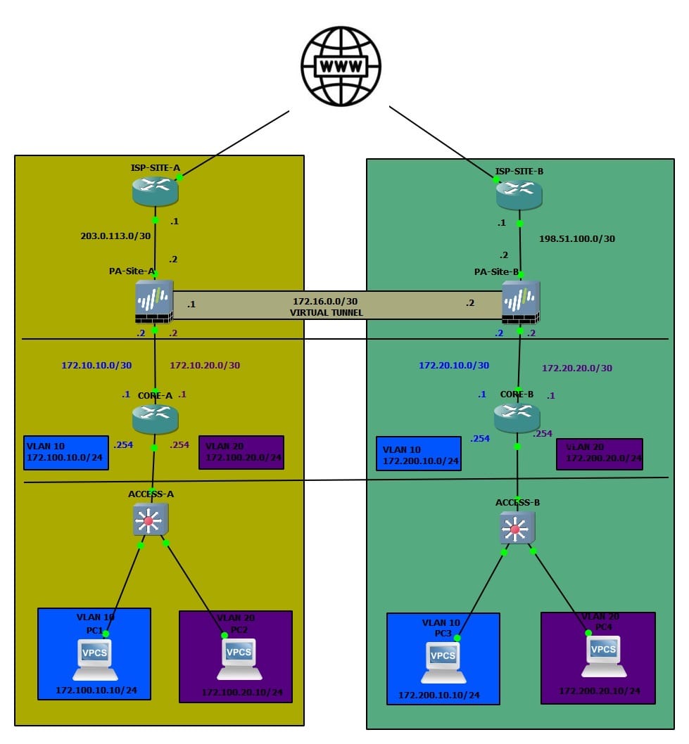
The design above is an example of a typical collapsed Core topology. This means that the Core layer handles both Core and Aggregation, without having a standard 3-tier Core > Aggregation > Access layer.
Access Layer
The Cisco IOS L2 switches are doing nothing but a bridging the frames between the end user devices and the Core. The uplink to the Core from the Access Switches is a sub interface with Dot1Q encapsulation:
interface Ethernet3/3
 switchport trunk encapsulation dot1q
 switchport trunk allowed vlan 10,20
 switchport mode trunk
 duplex auto
!
Core Layer
Both branches have 2 VLANs, VLAN 10 and VLAN 20. The L3 interface for each VLAN is on the Core. The IP schema for VLANs:
    172.
    100.
    10.
    0/24
172 = standard,
100 = site code,
10 = VLAN ID,
0/24 = subnet
Each VLAN is in its own dedicated VRF. The reason why I have done this that way is to be able to logically separate each VLAN into its own zone on the Palo Alto Firewall. Each VLAN maps to its own dedicated zone on the Palo Alto appliance, with a unique sub-interface per zone. This gives us granular control over inter-zone policies without any routing ambiguity between VLANs. It also means that we are able to utilise Dynamic Routing protocols on the /30 link. In this scenario, we will use OSPF to share routes between the Core and the Firewall.
Each VLAN has its own transit link (/30) between the Core and the Firewall. We will utilise this link to establish P2P OSPF adjacency between the Core and the Firewall (one OSPF area per VRF).
!
interface Ethernet0/0.10
 encapsulation dot1Q 10
 vrf forwarding VLAN_10
 ip address 172.100.10.254 255.255.255.0
 ip ospf 10 area 0.0.0.10
!

interface Ethernet0/0.20
 encapsulation dot1Q 20
 vrf forwarding VLAN_20
 ip address 172.100.20.254 255.255.255.0
 ip ospf 20 area 0.0.0.20
!

interface Ethernet1/3.10
 encapsulation dot1Q 10
 vrf forwarding VLAN_10
 ip address 172.10.10.1 255.255.255.252
 ip ospf network point-to-point
 ip ospf 10 area 0.0.0.10
!
interface Ethernet1/3.20
 encapsulation dot1Q 20
 vrf forwarding VLAN_20
 ip address 172.10.20.1 255.255.255.252
 ip ospf network point-to-point
 ip ospf 20 area 0.0.0.20
!
I tend to use the highest interface for uplinks and the lowest for downlinks.
Firewall
The Firewall has one Zone per VLAN, on top of the WAN zone that includes the interface facing the Internet Provider. Naturally, the link towards the Core layer has a matching sub interfaces with the adequate Dot1Q tag on the /30 link. The IPSec tunnel is contained within the zone dedicated to the remote site, in order to allow us to control the traffic policies depending on what traffic should be permitted across the tunnel.
OSPF Configuration
Core
Each VLAN is put into its own VRF. Each VRF consists of the actual VLAN L3 interface and the transit link, that allows us to establish a unique link per VRF, which we will use to transmit OSPF LSA's on. I will not be using the Area 0 for this deployment, since I only use the OSPF to advertise the directly connected routes from the Core (in this case VLAN interface).
CORE-A# show run  vrf VLAN_10
Building configuration...

Current configuration : 535 bytes
vrf definition VLAN_10
 !
 address-family ipv4
 exit-address-family
!
!
interface Ethernet0/0
 no ip address
!
interface Ethernet0/0.10
 encapsulation dot1Q 10
 vrf forwarding VLAN_10
 ip address 172.100.10.254 255.255.255.0
 ip ospf 10 area 0.0.0.10
!
interface Ethernet1/3
 no ip address
!
interface Ethernet1/3.10
 encapsulation dot1Q 10
 vrf forwarding VLAN_10
 ip address 172.10.10.1 255.255.255.252
 ip ospf network point-to-point
 ip ospf 10 area 0.0.0.10
!
router ospf 10 vrf VLAN_10
 passive-interface Ethernet0/0.10
!
!
end
I have associated both sub-interfaces with their respective areas. This will advertise the relevant prefix to be advertised over OSPF within the area that is associated with. Note that I have disabled LSA's towards the LAN facing interface since I am not expecting any OSPF-speaking devices to be present. I have also set the OSPF adjacency to be point-to-point since I am only expecting two devices to participate in each OSPF Area, therefore there is no need to use broadcast for this scenario.
Palo Alto
Under Network > Virtual Routers > default > OSPF we need to configure OSPF areas and more!
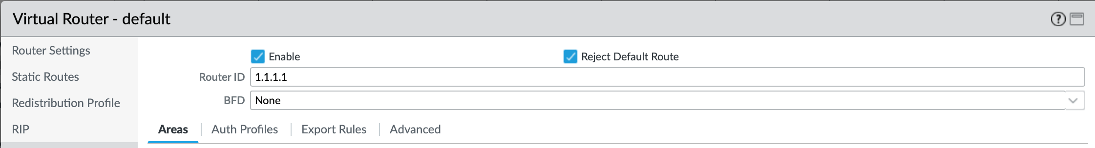
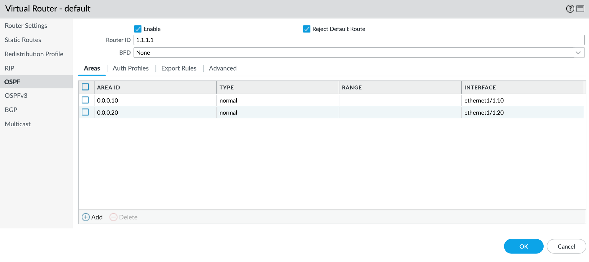
First and foremost, we need to enable OSPF by ticking the Enable box. I also like to toggle Reject Default Route in this case since I am not expecting a default route to be learned over OSPF in this scenario. It is a good practice to restrict default route re-advertisement as much as we can, as it can get messy real quick! For the Router ID, it is recommended to use a dedicated Loopback IP, however for this scenario I have used a dummy IP of 1.1.1.1. Let's create a new Area by clicking on Add.
As per the design, we are having one Area (or adjacency since its P2P) per sub-interface, so let's do that:
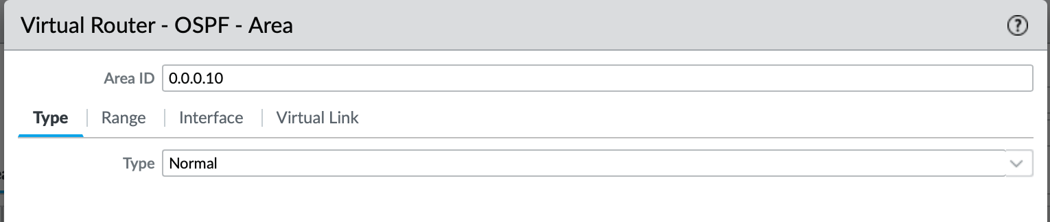
Type of the OSPF Area is Normal since is neither Stub nor NSSA.
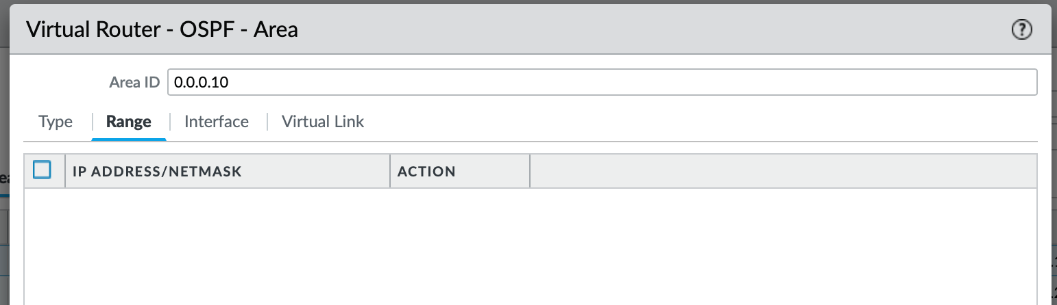
I will leave the Range empty since I will be re-distributing the default route to the OSPF. If I wanted to be granular about what routes I want to be re-advertised over this Area, I would have added the subnets here.
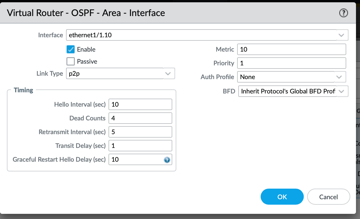
We also have to associated the interface that will participate in advertising the OSPF LSA's (Link State Advertisements). The Link Type of p2p matches the Core configuration since we are only expecting 2 neighbors per Area.
Once configured for both, we now have two interfaces configured as per below:
Default Route re-distribution
For any intra-protocol routes, you need to utilise re-distribution. Considering that at the moment our default route is static, we need to configure a profile that will match the 0.0.0.0/0 and re-distribute it towards the designated OSPF Areas of our choice. Of course, the same principle would apply for BGP-learned routes (which is the most common for the ISPs, especially in the Enterprise world, not so much for SOHO).
In order to create the Redistribution Profile, we can remain within the Network > Virtual Router > default (or a VR of your choice) and select Add.
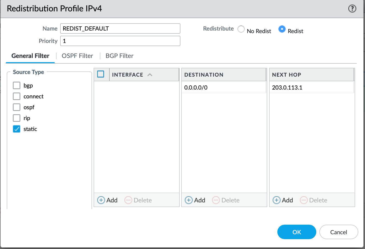
The Redistribution Profile is quite simple, within the Source Type you select the protocol that you are learning from, in our case it is a static. It is best to specify the destination prefix of the static route, followed by the next hop. We also need to toggle Redist to ensure that the Profile will be used for redistribution, otherwise - if No Redist is toggled, the prefixes associated will be discarded for the distribution.
Now we just need to associate the Redistribution Profile with the Export policy for the OSPF Areas. Let's go back to the OSPF field and select Export Rules tab. Now we just need to add the Re-distribution profile that we just created:
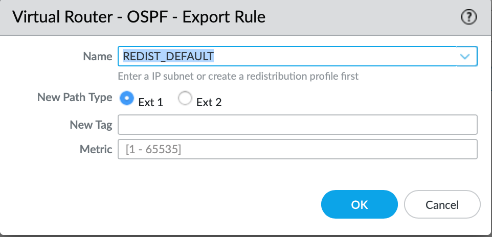
The New Path Type essentially means:
- Ext 1 - OSPF internal cost to ASBR + OSPF external metric.
- Ext 2 - OSPF external metric only
Since this is a default static route, none of these options are relevant to us. I will just leave it as Ext 2 for now which is the default option.
Route Validation
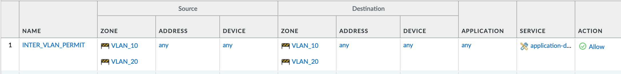
Now, we should be learning the default route from the Palo Alto in each VRF. This being said, before we start pinging the inter-VLAN hosts within the local site, it is worth to mention that I am allowing any traffic between the two VLAN zones on the Firewall.
Let's validate the routing table on the Site-A Core:
CORE-A#show ip route vrf VLAN_10

Routing Table: VLAN_10
Gateway of last resort is 172.10.10.2 to network 0.0.0.0

O*E2  0.0.0.0/0 [110/1] via 172.10.10.2, 00:04:25, Ethernet1/3.10
      172.10.0.0/16 is variably subnetted, 2 subnets, 2 masks
C        172.10.10.0/30 is directly connected, Ethernet1/3.10
L        172.10.10.1/32 is directly connected, Ethernet1/3.10
      172.100.0.0/16 is variably subnetted, 2 subnets, 2 masks
C        172.100.10.0/24 is directly connected, Ethernet0/0.10
L        172.100.10.254/32 is directly connected, Ethernet0/0.10
CORE-A#show ip route vrf VLAN_20

Routing Table: VLAN_20
Gateway of last resort is 172.10.20.2 to network 0.0.0.0

O*E2  0.0.0.0/0 [110/1] via 172.10.20.2, 00:04:42, Ethernet1/3.20
      172.10.0.0/16 is variably subnetted, 2 subnets, 2 masks
C        172.10.20.0/30 is directly connected, Ethernet1/3.20
L        172.10.20.1/32 is directly connected, Ethernet1/3.20
      172.100.0.0/16 is variably subnetted, 2 subnets, 2 masks
C        172.100.20.0/24 is directly connected, Ethernet0/0.20
L        172.100.20.254/32 is directly connected, Ethernet0/0.20
CORE-A#
The static route re-distribution is working great, let's validate the routing table on the Palo Alto to make sure that we are learning the VLAN's interfaces as we should!
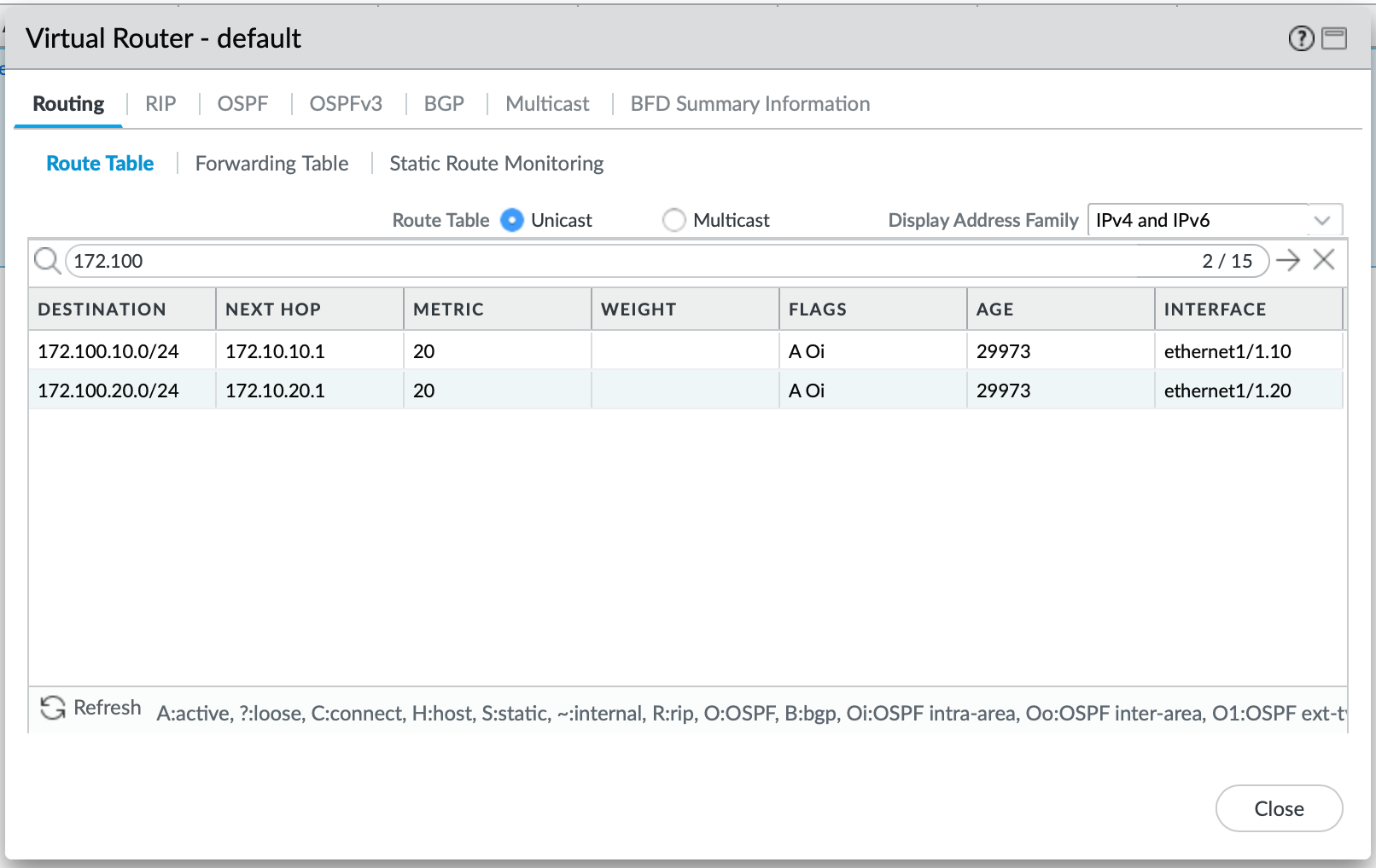
Looks like we are good, let's ping across from vPC-1 to vPC-2 (VLAN 10 to VLAN 20).
PC1> ping 172.100.20.10

84 bytes from 172.100.20.10 icmp_seq=1 ttl=61 time=24.495 ms
84 bytes from 172.100.20.10 icmp_seq=2 ttl=61 time=2.614 ms
84 bytes from 172.100.20.10 icmp_seq=3 ttl=61 time=2.973 ms
84 bytes from 172.100.20.10 icmp_seq=4 ttl=61 time=3.253 ms
84 bytes from 172.100.20.10 icmp_seq=5 ttl=61 time=3.494 ms

PC1>
Let's check the Session Browser on the Palo Alto Firewall:

We can see that the ingress interface for the traffic is ethernet1/1.10 within the VLAN 10 zone as expected, and its egress interface is ethernet1/1.20 which is a member of a VLAN 20 zone.
Closure
To recap, we have built a strong foundation for our next tasks in this series. Both sites are now learning routes between the Firewall and the Core. Our next step in the next article will be to build a VPN tunnel with BGP, in order to make sure that we can route across both sites dynamically.