

In my first Palo Alto article, I have touched on the design used for this lab. If you need to reference it, click on the bookmark below.
In this blog post, we will touch on how to establish a VPN tunnel from one Palo Alto firewall to another. We will then utilise the built tunnel's interface to establish the BGP adjacency between the two sites. The objective for this lab is to be able to ping from one of the vPC's in Site-A across to one of the vPC's in Site-B.
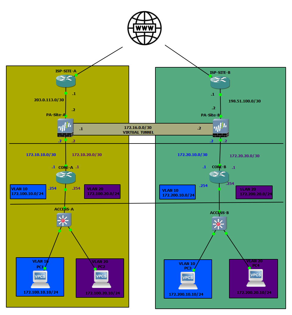
The topology used for this article:
IPSec Tunnel Configuration
Pre-reqs
First and foremost, we need to ensure that both sites are reachable. I have set up some static routes between the ISP routers to ensure that the branches can talk to each other. Each IPSec tunnel generally consists of the following:
- Tunnel interface (can be used for routing within the tunnel)
- IKE Gateway (contains public IP details of the destination, at a minimum)
- IKE and IPSec Crypto Profiles (have to match on both sites)
- Authentication (pre-shared-key or certificate-based)
Now that we have the very high-level list of requirements covered, let's get to how to prep the tunnel. Let's start with creating the Tunnel interface.
Tunnel Interface
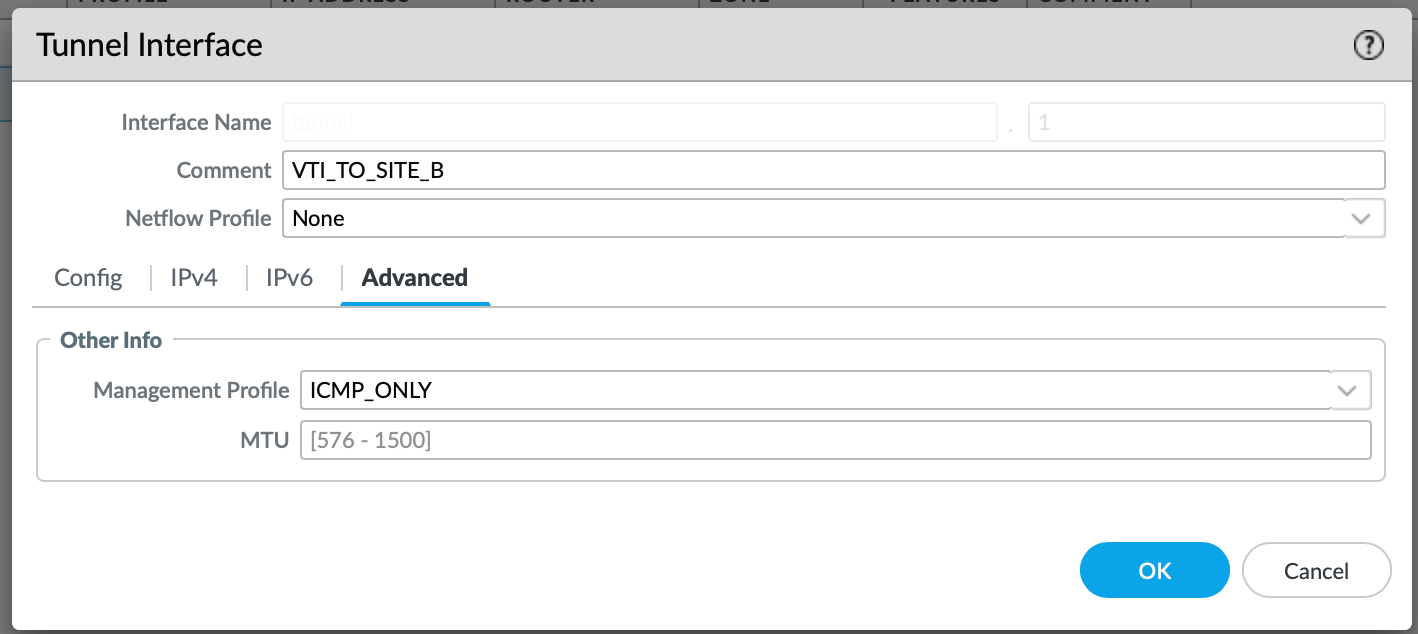
Under Network > Interfaces > Tunnel, select Add.
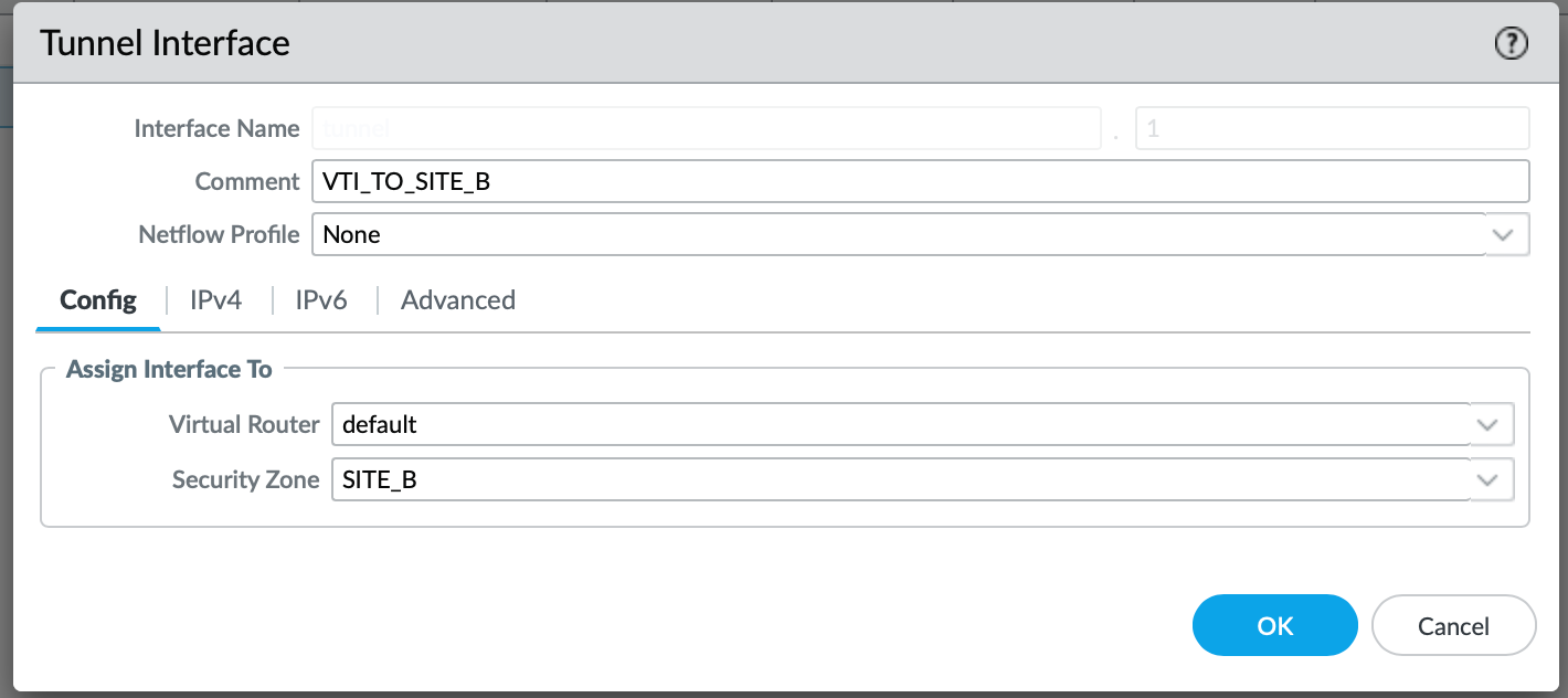
Make sure to associate the Virtual Router (default, or any VR that is relevant to you). Otherwise, the Interface will not come up!
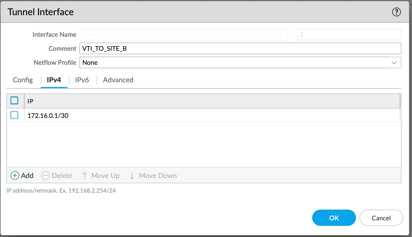
Now, based on the diagram above, we need to IP the interface with an address 172.16.0.1/30 for Site A.
I also like to associate the Management Profile for some interfaces, this helps me to validate if the link is up by pinging it. I just tend to enable ICMP:
IKE Gateway
Navigate to Network > Network Profiles > IKE Gateway and select Add.
We need to give it a name. I tend to keep it as specific as I possibly can. The version of the IKE could either be 1 or 2; however it is best practice to stick to version 2. It provides faster connection speeds and enhanced security, which is superior to IKE v1 at this point.
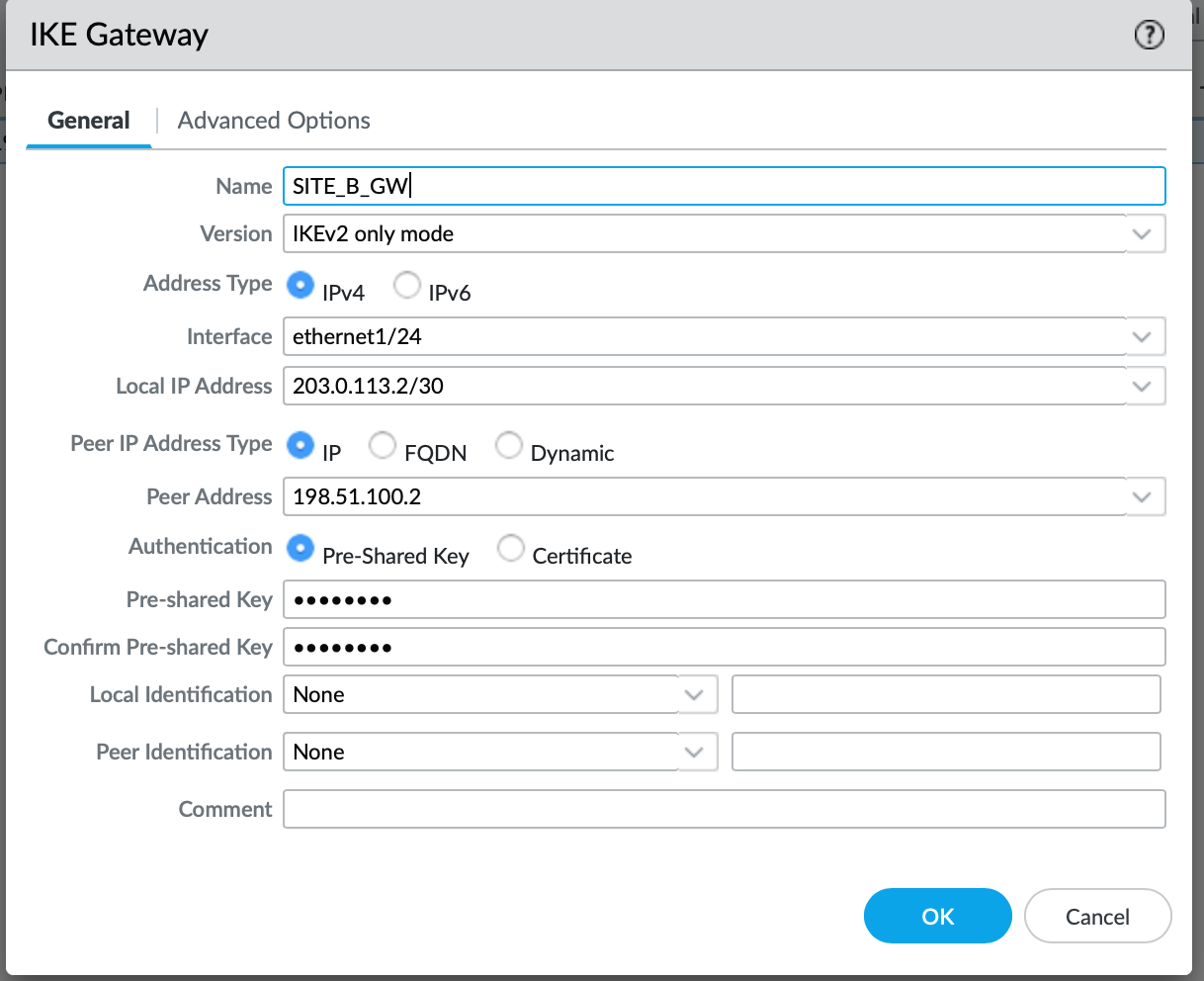
For the interface, you need to select the Interface that will be used to establish the tunnel. In our case, it is a public-facing one. Peer IP address is essentially a public IP address (in our case) used by the remote side. It's a mirror of our Local IP address (meaning on the remote side, the Local IP will be our Remote IP). Since we are not using a certificate for authentication in this scenario, we need to specify a Pre-shared-key, which has to match on both sites.
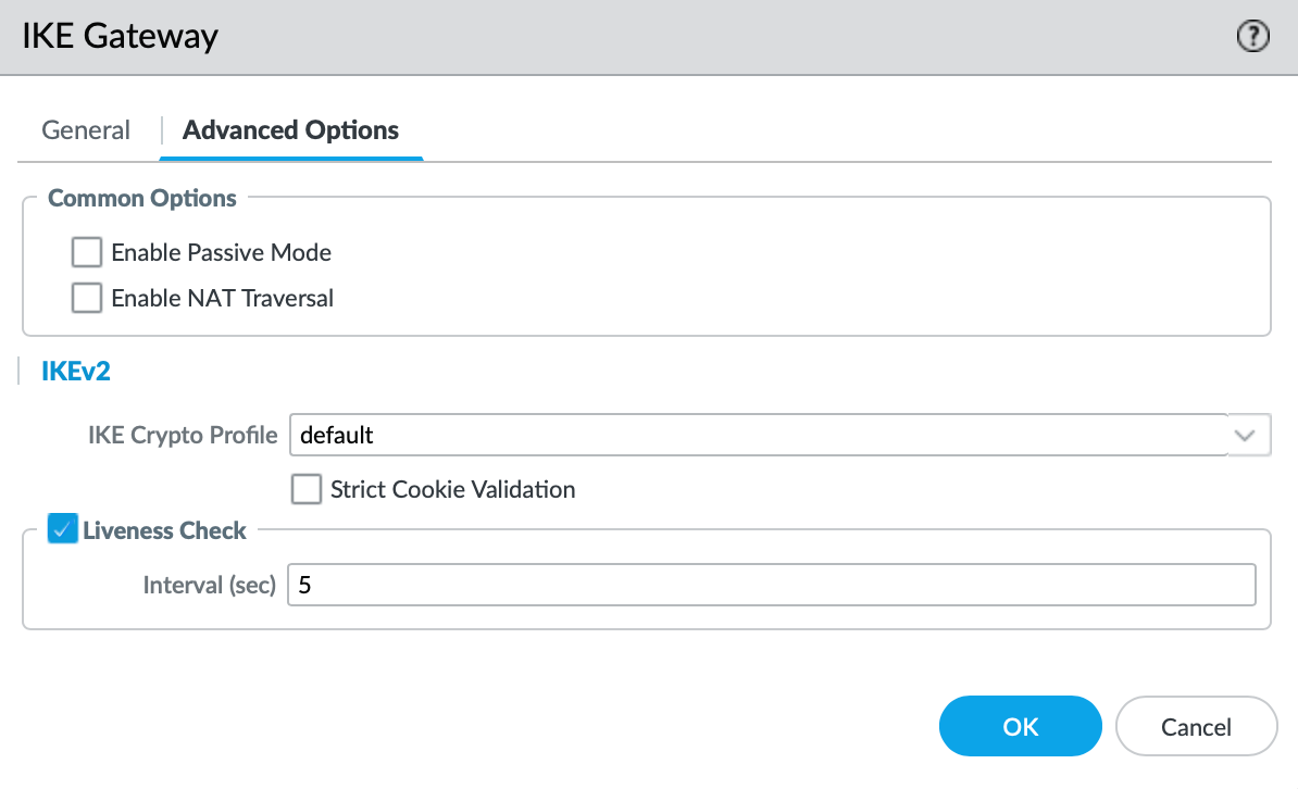
Under Advanced Options, we have an option to select a set of Crypto Profiles. We will stick to the default for this use case, but more on that below.
IPSec Tunnel
Under Network > IPSec Tunnels, we need to Add a new tunnel, which nicely ties all of the above together.
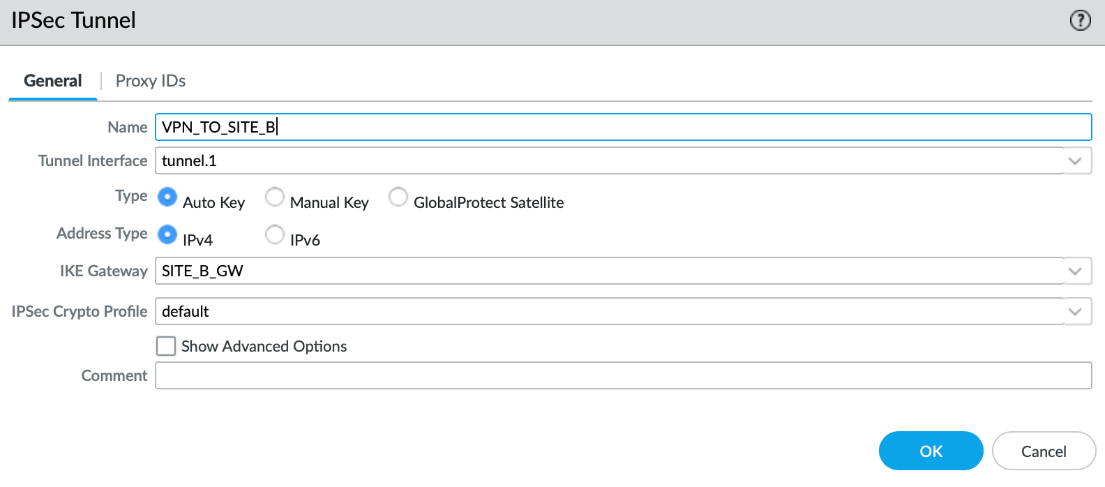
Now we just need to reference every object that we have created so far. The only element that's worth pointing out is the Crypto Profile. As with the IKE, I am using the default profile, however it is a best practice to use the most secure protocols that are supported by both devices participating in the IPSec tunnel.
If you are unsure what protocols to use, feel free to reference the National Cyber Security Centre recommendations:
Validating the tunnel
As mentioned above, I have pre-configured the remote Firewall already; therefore, the tunnel should now come up.
Now, what do I mean by that? We need to initiate the traffic over the tunnel in order for the Phase 1 and 2 (IKE and IPSec) to establish. We can do this by pinging the remote IP of the VTI (Virtual Tunnel Interface). This should bring the tunnel up.
admin@Site-A-PA> ping source 172.16.0.1 host 172.16.0.2
PING 172.16.0.2 (172.16.0.2) from 172.16.0.1 : 56(84) bytes of data.
64 bytes from 172.16.0.2: icmp_seq=1 ttl=64 time=13.6 ms
64 bytes from 172.16.0.2: icmp_seq=2 ttl=64 time=5.10 ms
64 bytes from 172.16.0.2: icmp_seq=3 ttl=64 time=3.75 ms
64 bytes from 172.16.0.2: icmp_seq=4 ttl=64 time=4.07 ms
64 bytes from 172.16.0.2: icmp_seq=5 ttl=64 time=3.64 ms
64 bytes from 172.16.0.2: icmp_seq=6 ttl=64 time=2.71 ms
64 bytes from 172.16.0.2: icmp_seq=7 ttl=64 time=4.20 ms
^C
--- 172.16.0.2 ping statistics ---
7 packets transmitted, 7 received, 0% packet loss, time 15ms
rtt min/avg/max/mdev = 2.710/5.300/13.640/3.468 ms
admin@Site-A-PA>
We can validate the tunnel by issuing the show vpn ike-sa
admin@Site-A-PA> show vpn ike-sa

There is no IKEv1 phase-1 SA found.

There is no IKEv1 phase-2 SA found.


IKEv2 SAs
Gateway ID      Peer-Address           Gateway Name                                                    Role SN       Algorithm             Established     Expiration      Xt Child  ST
----------      ------------           ------------                                                    ---- --       ---------             -----------     ----------      -- -----  --
1               198.51.100.2           SITE_B_GW                                                       Init 2        PSK/ DH2/A128/SHA1    Apr.19 23:40:46 Apr.20 07:40:46 0  1      Established

IKEv2 IPSec Child SAs
Gateway Name                                                    TnID     Tunnel                                                          ID       Parent   Role SPI(in)  SPI(out) MsgID    ST
------------                                                    ----     ------                                                          --       ------   ---- -------  -------- -----    --
SITE_B_GW                                                       1        VPN_TO_SITE_B                                                   790      2        Init 8B9009CB CB48B35F 00000316 Mature

Show IKEv2 SA: Total 1 gateways found. 1 ike sa found.
As per above, we can validate that a) the IKE is established and Phase 2 has exchanged cookies. Now we can utilise the /30 link to configure BGP.
BGP
Initial Setup
Now that we have the IP reachability between the VTI's across two sites, we can make a start with the BGP configuration. Inside of Network > Virtual Router > default > BGP, we need to do the following:
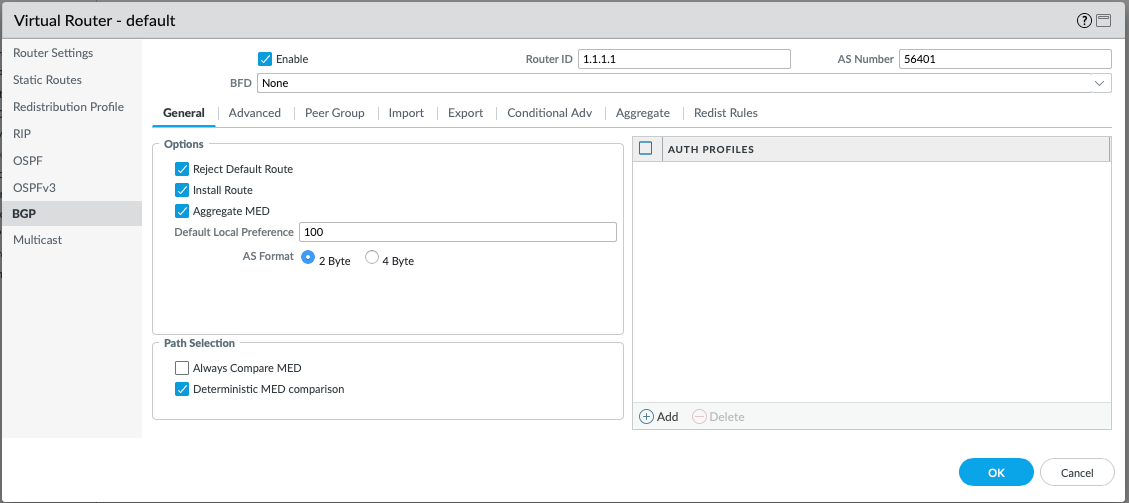
Firstly, the BGP protocol has to be enabled by ticking the Enable box. The Router ID used will be exactly the same as for the OSPF. For the AS Number, I have gone with 56401 for Site A, and 56402 for Site B. I have used public AS range in this case, however this is not an issue, since the BGP peering is not over the Internet, but over the private VPN. I am going to leave the Reject Default Route toggled on since I am not expecting any default routes to learn via BGP. It is also crucial to toggle Install Route, otherwise they BGP-learned routes will never be injected into the routing table.
Peer Group
Under the Peer Group tab, we need to define our neighbour(s). A single Peer Group can consist of one or more BGP neighbours. In our case, we only are expecting one neighbour so far.
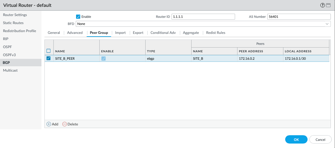
Select Add, and you will be prompted with the following:
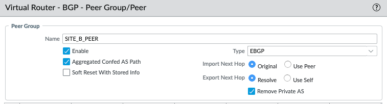
We need to give the Peer Group a name and enable it. Otherwise, we can move on to adding the Peer, which will be the VTI of the Site-B (172.16.0.2):
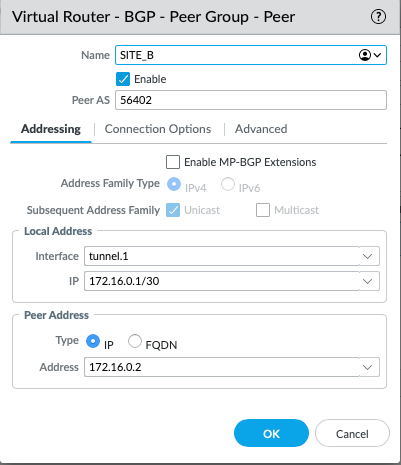
After we have named it accordingly, we need to give it the AS number that we have allocated to Site-B. As mentioned above, we have gone for with the AS of 56401 for Site A, and 56402 for Site B. The Local Interface used for the peering will be tunnel.1, and naturally, the Peer Address is the IP address of the remote tunnel.1.
Redistribution Profile
Since the LAN facing routes are learned over OSPF, we need to create a redistribution profile that will re-advertise any OSPF learned routes over BGP.
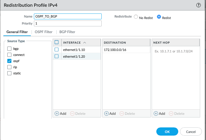
What are we saying here is, any routes sourced from the OSPF, from the interface of ethernet1/1.10 and ethernet1/1.20, destined to 172.100.0.0/16 (or longer), redistribute.
Firewall Policy
I have also ensured that all traffic from both local subnets (VLAN_10 and VLAN_20) is permitted to SITE_B. The Firewall rule includes all zones in source and destination since I am not too worried about what traffic is being permitted within the lab environment.

BGP Validation
Now that the config is pushed and everything is configured, let's validate if the BGP has established and if the routes are learned. We can easily check that under Network > Virtual Routers > More Runtime Stats > BGP > Peer:
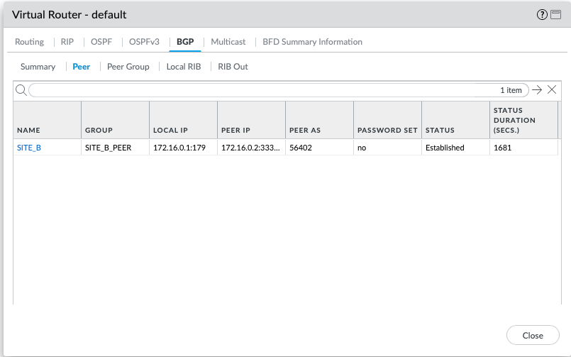
The Status is established, which is what we want. Now, let's validate the Local RIB and RIB Out, which refer to the staging tables that hold routing information before it is processed or advertised. I essence, Local RIB is a table that holds routes learned + local, and Rib Out is the table that shows routes that are being advertised to the BGP peers. If the routes don't exist in either of those, you are likely not advertising/receiving routes properly.
Local RIB
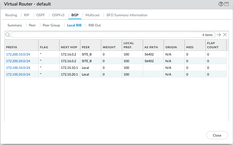
Happy days, it appears that peer of SITE_B is advertising the local VLANs to us, now let's validate if we advertise our local routes to SITE_B.
Rib Out
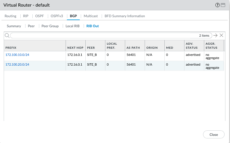
Looks like everything is correct, let's validate IP reachability from vPC1 to vPC3.
PC1> ping 172.200.10.10

84 bytes from 172.200.10.10 icmp_seq=1 ttl=60 time=6.705 ms
84 bytes from 172.200.10.10 icmp_seq=2 ttl=60 time=5.237 ms
84 bytes from 172.200.10.10 icmp_seq=3 ttl=60 time=5.742 ms
84 bytes from 172.200.10.10 icmp_seq=4 ttl=60 time=5.208 ms
84 bytes from 172.200.10.10 icmp_seq=5 ttl=60 time=5.382 ms
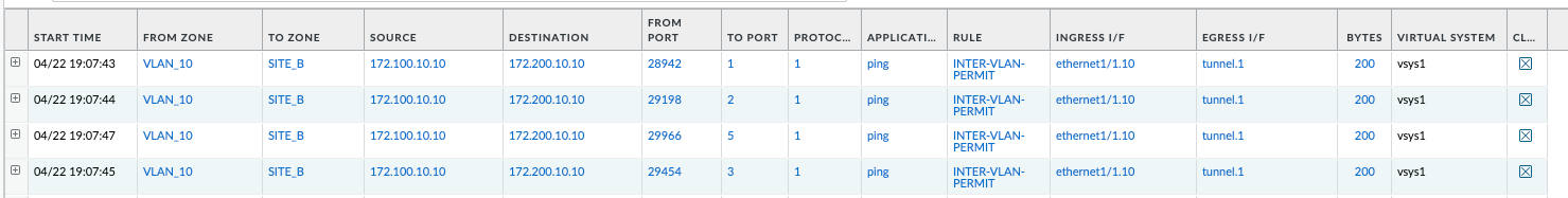
It looks like we can ping just fine. We can also validate the exact source and destination zones via the Session Browser lookup. This confirms that the traffic is in fact coming from VLAN_10, to SITE_B, ingress from ethernet1/1.10, egress to tunnel.1.
Closure
And just like that, we now have fully functional dynamic routing across two sites, including OSPF within the local network and BGP across the two sites. We can now easily add new subnets/sub-interfaces within the 172.16.0.0/16 range, which will automatically be advertised across the two sites for ease of reachability. Thanks to sub-interface segmentation, we can define custom Firewall policies depending on the access criteria required for each zone.
In the next article, I will explain how to handle BGP with redundancy using the BFD protocol. We will add an additional ISP for each site, which will give us some redundancy and ensure that the site can remain operational in the event of an ISP failure.